
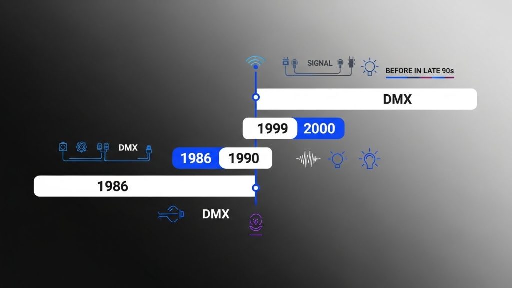
DMX512 is a communication signal used to control what are commonly referred to as Intelligent Lights by universal or specific DMX controllers. It started out as USITT DMX512, then was abbreviated to DMX512 and is now most often called DMX.
The abbreviation DMX512 stands for Digital Multiplex Signal that can control up to 512 channels. This language was created by the United States Institute for Theater Technology (USITT) to simplify and unify theater lighting systems. Before DMX was created, the only lighting control system was analog which required one individual wire to be run from the controller to each light fixture or dimmer pack.
It is important to understand that DMX is a communication signal only and does not supply power to the fixtures. All DMX light fixtures and dimmer packs require their own power supply. DMX is now recognized world wide as the standard communication language for theater and night club lighting and now even some fog machines.
A DMX system consists of four main components that work together to transmit and receive lighting control signals.
This generates and sends the DMX signal that controls the lights
This cable carries the DMX signal from one device to another.
These devices receive and respond to the DMX signal.
The last device in the chain ends the signal to prevent data reflection.
Connecting a DMX system is simple if you follow these three important steps.
Link the controller, light fixtures, and dimmer packs using high-quality DMX cables.
Assign the correct DMX address to every fixture or dimmer pack.
Do not power ON any device until all fixtures are connected and properly addressed.
Understanding the difference between DMX cables and microphone cables.
DMX and microphone cables are often confused, but in real-world use, many microphone cables work perfectly well for transmitting digital lighting signals. Before DMX became standard in the late 1990s, most signal-based lighting systems used regular mic cables.
Companies like NSI were using MICROPLEX signals long before DMX existed, and all communication ran through 3-pin microphone cables.
The truth:
DMX cables are often misunderstood. Over the years, both microphone cables and DMX cables have been used successfully for digital lighting signals. What truly matters is cable quality, proper pin-wiring, and keeping connectors free from damage.
Both can work for digital signals. What matters is quality and correct pin wiring.
Mid to high-grade mic cables often perform as well as DMX cables.
Companies like NSI used 3-pin mic cables for MICROPLEX long before DMX became standard.
Both 3-pin and 5-pin connectors use the same essential signal pins (1-ground, 2-negative, 3-positive).
Each light fixture and dimmer pack must have an address in order to receive data from the controller. Assigning an incorrect address to your light fixture is as fatal as putting the wrong address on your electric bill payment. In both cases the lights won’t come on!! DMX address mistakes are a big cause of problems with new systems and new human operators. Bad addresses on fixtures cause problems such as gobo change instead of mirror movement, color change instead of gobo change, or no response at all. Setting DMX addresses is sometimes very simple by following manufacturer instructions and sometimes very difficult when no instructions are available.
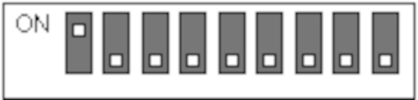
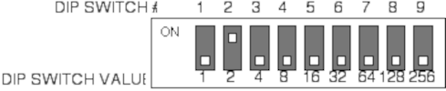
Address values are easy to remember. Starting on the left and moving right, each dip switch has a value twice as large as the switch at its left.

The address for a DMX light fixture equals the sum of the value for all dip switches in the ON position. In the picture above, the address selected is 1.

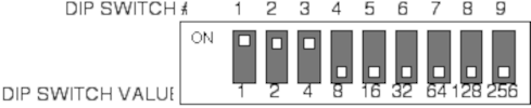

Always start with the highest-value DIP switch and move downward.
Pick the biggest number first, then add smaller values until you reach your exact DMX address.
You might find these little switches easier to manipulate with a small screwdriver or a writing pen.
Address values are easy to remember. Starting on the left and moving right, each dip switch has a value twice as large as the switch at its left.
The address for a DMX light fixture equals the sum of the value for all dip switches in the ON position. In the picture above, the address selected is 1.
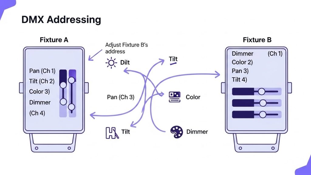
Determining DMX addresses on fixtures
This is where the confusion starts. Many intelligent scanning lights use 4 channels; 1 for the gobo wheel, 1 for the color wheel, 1 for left to right mirror movement and 1 for up and down mirror movement.
So why does the second fixture need to be addressed 13 instead of 5?
Almost all manufacturers make DMX intelligent lights that OCCUPY more channels than they USE.
To properly test a DMX lighting fixture, you should begin with a single unit, identify how each controller slider affects it, and then add more fixtures to confirm correct addressing and behavior.
Attach a single light fixture to the DMX controller using one DMX cable and set its address to 1.
Power on the controller and move each slider to identify which action it triggers on the light (color, gobo, movement, etc.).
Connect another fixture in daisy-chain mode and set it to address 1. Both fixtures should mirror each other’s movements.
If you want each light to behave differently, assign each fixture a different DMX address.
DMX addressing becomes confusing because many intelligent lights use fewer channels but occupy more. This means the next fixture often needs a much higher starting address than expected. To find the correct spacing, test one fixture at address 1 and note which sliders control which functions. Then connect a second fixture and experiment by shifting its address upward (2, 3, 4…) until both behave correctly. The number where both fixtures work properly reveals how many channels your light occupies.
Once the channel occupancy is known, addressing becomes simple. For example, if a fixture occupies 6 channels, you would assign the first fixture to address 1, the second to 7, and the third to 13. This prevents overlapping functions and keeps the DMX chain working smoothly.
Different DMX controllers come with different numbers of sliders, which means their channel mapping may not match every fixture perfectly. Some fixtures place mirror movement or color functions on different channel numbers. To fix this, you can creatively adjust DMX addresses so the same sliders on the controller trigger the same functions on all lights.
By shifting the address of one fixture slightly forward, you can sync functions like left/right or up/down movement across different lights—even if their original channel layouts don’t match.
DMX lines should ideally be terminated to prevent signal reflections at the end of the daisy chain. Although many systems still work without termination, using a terminator helps reduce errors. Most fixtures made after 1999 include built-in termination, making the process simple and more reliable.